Author Archive: admin
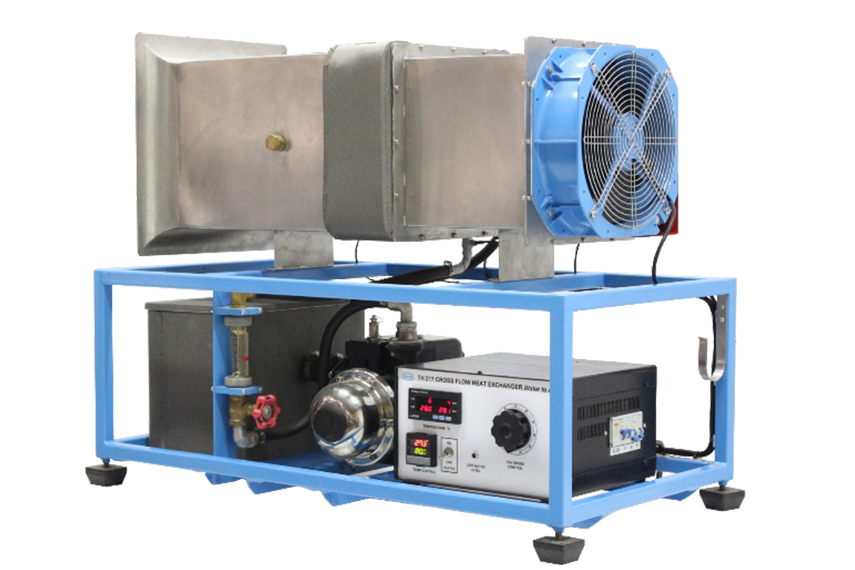
TH 217 CROSS FLOW HEAT EXCHANGER, Water-to-Air
The apparatus is for studying heat transfer from hot water to cross flow air such as in automobile radiator.
The unit consists of an air duct with outlet damper, an automotive radiator, an axial flow fan and a service module. The module provided hot water tank with transfer pump and control and measuring instruments.
Instruction manual is also supplied.
Demonstration of heat transfer under parallel and counter flow.
Determination of heat transfer coefficient.
Effects of flow rate and temperature difference.
|
||
| - Type | : Finned tube | |
| - Material | : Copper/Aluminum (Cu/Al) | |
| : Heat transfer area approximately 30,000 cm2 | ||
|
: 250 x 250 mm | |
|
||
| - Power consumption | : 180 W | |
| - Maximum flow rate | : Approx. 45 LPM | |
|
: Axial, adjustable speed | |
| - Power consumption | : Approx. 0.12 kW | |
| - Maximum flow rate | : Approx. 30 m3/min |
- Service module consisting of :
| - Hot water pump | : 1 | |
| - Heater | : 3000 W. | |
| - Air flow rate | : Portable anemometer | |
| - Flow meters | : Hot water. | |
| - Sensors with digital display | : Temperature for hot water inlet and outlet. | |
| for air inlet and outlet |
- Power supply : 220V 1Ph 50 Hz. Other power supply is available on request.
Net (unpacked) shipping dimensions WxLxH : 55 x 120 x 80 cm.
Net weight : Approx. 70 kg
| Computer Interface (computer not included) |
| This includes TH217S and significant sensor(s) instead of analog measuring instrument(s), data acquisition (capture, display, graph and/or data export), additional software function for real-time data logging with computer interface unit and WiFi feature for data logging and real-time display remotely on smartphone (iOS and Android) | |
| Computer Control (computer not included) |
| This includes TH 217-050 with the additional accessories for control function and additional software function for equipment controls by computer |
- Other optional equipment, please contact manufacturer ([email protected])
| Learning Software |
to support both online/offline training with data calculation and analysis by manual data entry from analog measuring instruments. |
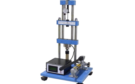
TM 445 CIRCULAR DIAPHRAGM
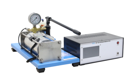
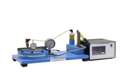
The equipment is used for studying the stress and deflection of a thin diaphragm.
The circular aluminum alloy diaphragm is clamped around its edge by two heavy steel flanges. Internal pressure is applied to the diaphragm by a hydraulic hand pump. Pressure in the diaphragm is indicated on a pressure gauge. A dial gauge is fitted onto a cross bar to measure the diaphragm surface profile. Scale on the cross bar indicates the dial gauge position.
Strain gauges are of the same gauge factor and the gauges are fitted onto the diaphragm at different angles and radii. Each strain gauge is wired to form a full bridge with temperature compensation gauge and zero adjustment in a bridge box with strain gauge indicator.
Instruction manual is also included.
Deflection of circular diaphragm under pressure
Strains on the diaphragm surface under pressure
| |
| - Effective diameter | : 200 mm |
| - Maximum internal pressure | : 60 kN/m2 |
| : 1 kg/cm2 |
| : 8 ea. |
| : 0-20 mm x 0.01 mm graduation |
| : 8 channels |
| : 220V, 1 Ph, 50Hz. Other power supply is available on request. |
- Net (unpacked) Shipping Dimensions WxLxH: 60 x 65 x 41 cm
- Net Weight: Approx. 31 kg
| Computer Interface (computer not included) |
| This includes TM445S and significant sensor(s) instead of analog measuring instrument(s), data acquisition (capture, display, graph and/or data export), additional software function for real-time data logging with computer interface unit and WiFi feature for data logging and real-time display remotely on smartphone (iOS and Android) |
- Other optional equipment, please contact manufacturer ([email protected])
| Learning Software |
| to support both online/offline training with data calculation and analysis by manual data entry from analog measuring instruments. |

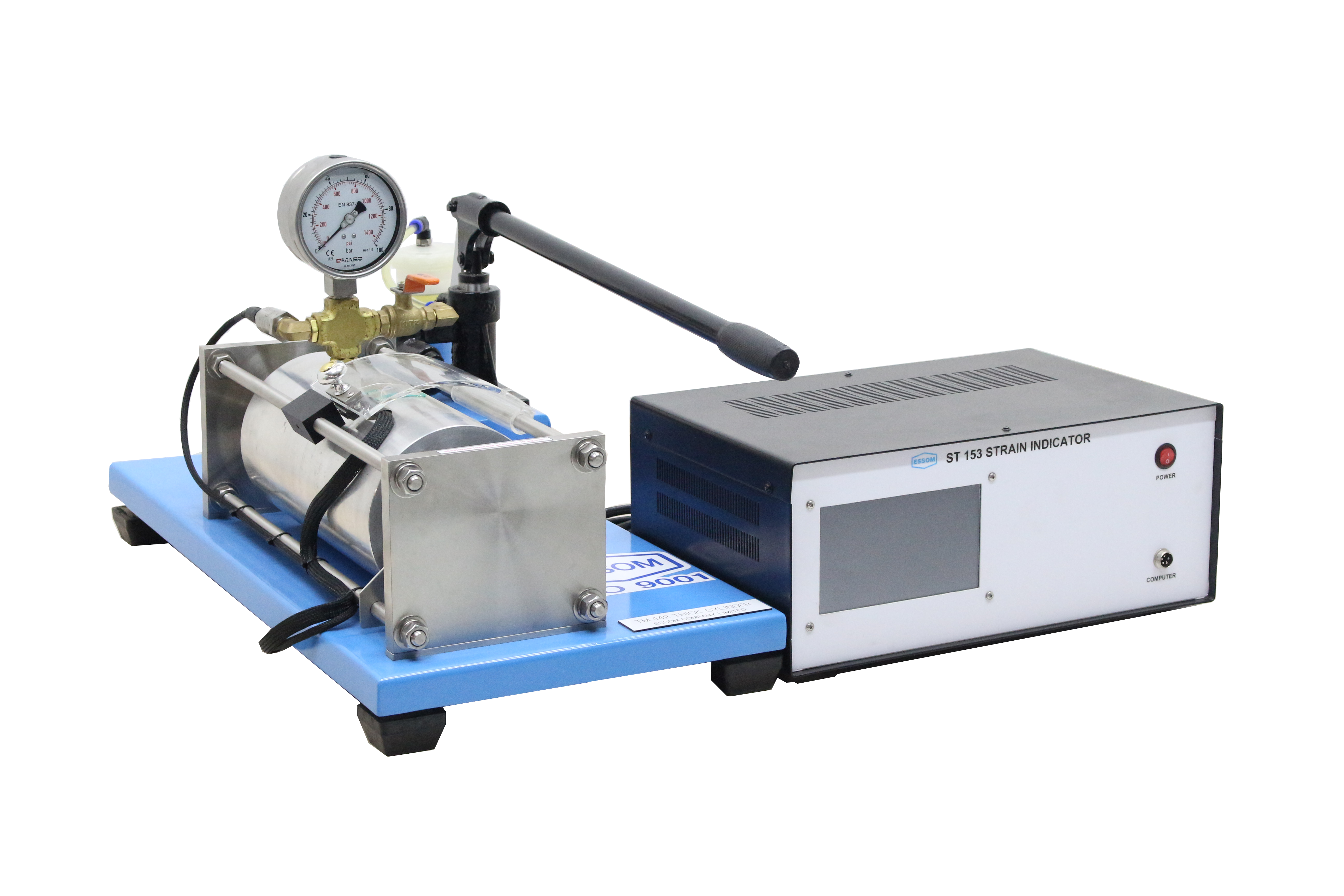
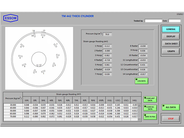
TM 442 THICK CYLINDER
The equipment is used for studying a stress profile in the wall of a thick cylinder.
Two halves of thick aluminum alloy cylinders are cemented and clamped together. A hand operated hydraulic pump transmits pressure to the inside of the cylinders via the clamping bolt. The pressure is indicated by a pressure gauge.
Strain gauges are of the same gauge factor and the gauges are attached radially and circumferentially along the wall thickness and filled with jointing material. Additional strain gauges are attached on the inside and outside surfaces of the cylinder. Each strain gauge is wired to form a full bridge with temperature compensation gauge and zero adjustment in a bridge box with strain gauge indicator.
Instruction manual is also included.
Measurement of strains, hence stresses, along the cylinder wall thickness.
Comparison of the actual strain readings with theoretical values.
| |
| - Length | : 300 mm |
| - Outer diameter | : 180 mm |
| - Maximum internal pressure | : 7 N/mm2 |
| : 100 kg/cm2 |
| : 14 ea. at different angles. |
| : 16 channels |
| : 220V, 1 Ph, 50Hz. Other power supply is available on request. |
- Net (unpacked) Shipping Dimensions WxLxH: 60 x 65 x 48 cm
- Net Weight: Approx. 48.5 kg
| Computer Interface (computer not included) |
| This includes TM442S and significant sensor(s) instead of analog measuring instrument(s), data acquisition (capture, display, graph and/or data export), additional software function for real-time data logging with computer interface unit and WiFi feature for data logging and real-time display remotely on smartphone (iOS and Android) |
- Other optional equipment, please contact manufacturer ([email protected])
| Learning Software |
| to support both online/offline training with data calculation and analysis by manual data entry from analog measuring instruments. |

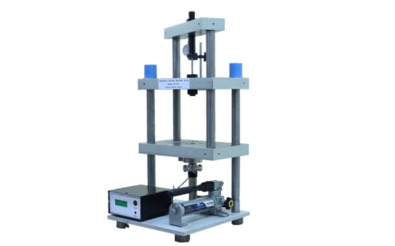
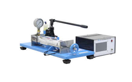
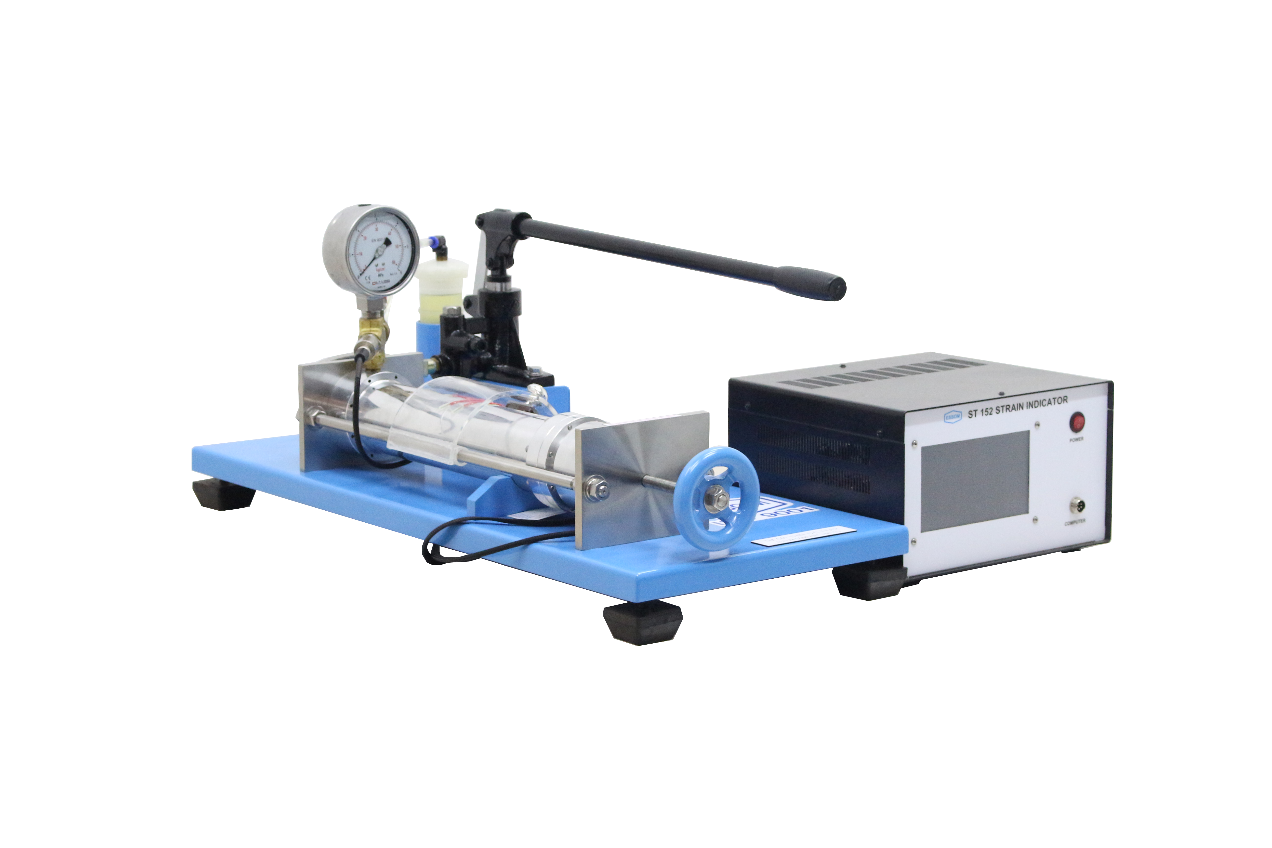
TM 441 THIN CYLINDER
This equipment is used for studying the stresses in a thin wall cylinder.
A thin wall aluminum alloy cylinder is mounted on a rigid steel frame. Internal pressure is applied to the cylinder by means of a hydraulic hand pump with oil reservoir. Pressure in the cylinder is indicated on a pressure gauge. A screw is attached on a frame to open or close one side of the cylinder. When the cylinder is open, only circumferential stress occurs on the cylinder. When the cylinder is closed, both circumferential and axial stresses occur.
Strain gauges are of the same gauge factor and the gauges are fixed onto the cylinder at different angles. Each strain gauge is wired to form a full bridge with temperature compensation gauge and zero adjustment in a bridge box with strain gauge indicator.
Instruction manual is also included.
Measurement of strains and stresses under internal pressures.
Determination of Young’s modulus a Poisson’s ratio.
Comparison of theoretical stresses and strains with experimental values.
| |
| - Length | : 360 mm |
| - Outer diameter | : 80 mm |
| - Maximum internal pressure | : 3.5 N/mm2 |
| : 50 kg/cm2 |
| : 6 ea. at different angles. |
| : 8 channels |
| : 220V, 1 Ph, 50Hz. Other power supply is available on request. |
- Net (unpacked) Shipping Dimensions WxLxH: 60 x 65 x 48 cm
- Net Weight: Approx. 35 kg
| Computer Interface (computer not included) |
| This includes TM441S and significant sensor(s) instead of analog measuring instrument(s), data acquisition (capture, display, graph and/or data export), additional software function for real-time data logging with computer interface unit and WiFi feature for data logging and real-time display remotely on smartphone (iOS and Android) |
- Other optional equipment, please contact manufacturer ([email protected])
| Learning Software |
| to support both online/offline training with data calculation and analysis by manual data entry from analog measuring instruments. |

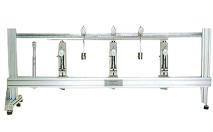
TM 415 BEAM APPARATUS
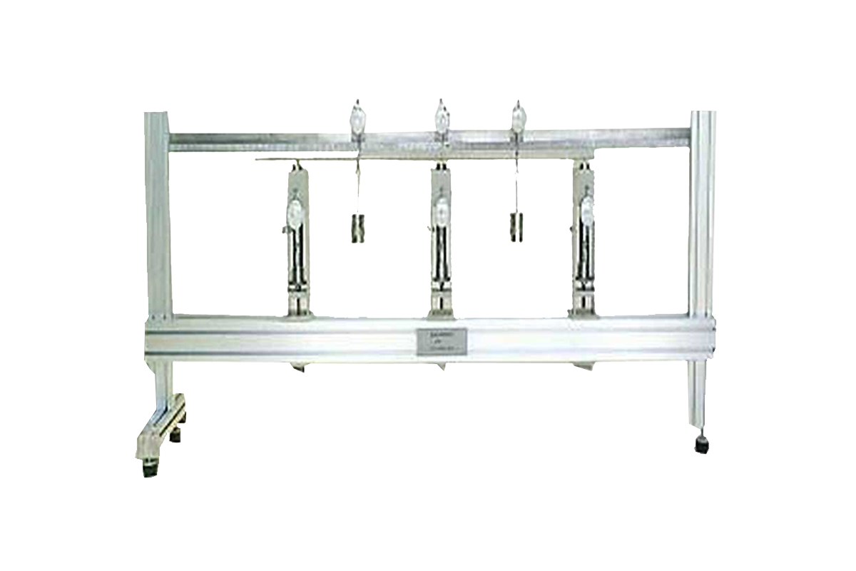
This beam apparatus is of a universal design for use in a wide range of beam experiments with simple, built-in and sinking supports measuring of, point loads, support reactions and beam deflections.
The beam frame consists of a stainless steel angle upper cross member and two aluminum profile lower cross members, bolted to the support columns with footings. Three spring load cells with height adjustment and a cantilever support can slide along the lower members and can be clamped at any point. Dial indicators can slide along the upper member and can be clamped at any point. Linear scale is attached to the upper member to indicate the positions of load cells, loads, supports and dial indicators.
The spring load cell has a hardened steel tube sliding in a bushing with hardened steel knife edge on top of the tube. The tube rests on a coil spring on a lead screw which provides direct load reading via a dial indicator. The height of the knife edge can be fixed at any position by a wing bolt.
Instruction manual is also included.
Deflection of beams with various supports and point loads.
Deflection of cantilever beam
Determination of flexural rigidity and elastic modulus.
Verification of static equilibrium.
Verification of the bending equation M/I = E/R
Beams with sinking supports.
Statically indeterminate beam with different loadings and supports.
| : Aluminum profile and stainless-steel angle 1400 mm. long |
| : 3 |
| : 1 |
| : 4 |
| : 1 lot |
| : 1200 mm |
| |
| - Mild steel | : 3 |
| - Aluminum and brass | : 1 |
| : 3x 0-20 mm range, 0.01 mm graduation |
- Net (unpacked) Shipping Dimensions WxLxH: 15 x 140 x 70 cm
- Net Weight: Approx. 55 kg
Beams of other sizes and materials can be supplied on request.
TM415-050 Computer Interface (computer not included)
This includes TM415S and significant sensor(s) instead of analog measuring instrument(s), data acquisition (capture, display, graph and/or data export), additional software function for real-time data logging with computer interface unit and WiFi feature for data logging and real-time display remotely on smartphone (iOS and Android)
Other optional equipment, please contact manufacturer ([email protected])
| Learning Software |
| to support both online/offline training with data calculation and analysis by manual data entry from analog measuring instruments. |
TM 411 STRUT BUCKLING APPARATUS
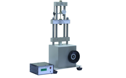
This bench top apparatus is used for studying buckling on struts under various end conditions.
The apparatus consists of two vertical columns where load is applied by a screw via a sliding support. Strut support for knife edge or built-in is a cylinder in a socket. Each strut has end conditions for knife-edge or built-in. Load on the strut is measured by a load cell and deflection is measured by a dial gauge. Side loading is by a weight hanger and weights. Height of loading beam is adjustable to accommodate different strut lengths.
Instruction manual is also included.
Determination of flexural rigidity and comparison with theoretical value.
Determination of flexural rigidity under different end conditions.
Determination of load VS deflection and crippling loads for strut of different
lengths and cross sections.
Effects of side load and eccentric loading.
| : 2 columns and sliding cross member with loading screw. |
| : 750 mm |
| : Force digital display |
| : 0-20 mm. x 0.01 mm. graduation. |
| |
| : 1 lot. |
| : 2 Knife edges |
| : 2 Built-in | |
| |
| - Mild steel | : 6 ea. different lengths. |
| - Aluminium and brass | : Thickness (approx.) 6 mm, Width (approx.) 19 mm, Length: 750 mm |
| : 220V, 1Ph, 50Hz. Other power supply is available on request. |
- Net (unpacked) Shipping Dimensions WxLxH: 25 x 25 x 105 cm
- Net Weight: Approx. 20 kg
Struts of other sizes and materials are available on request.
TM411-050 Computer Interface (computer not included)
This includes TM411S and significant sensor(s) instead of analog measuring instrument(s), data acquisition (capture, display, graph and/or data export), additional software function for real-time data logging with computer interface unit and WiFi feature for data logging and real-time display remotely on smartphone (iOS and Android)
Other optional equipment, please contact manufacturer
| Learning Software |
| to support both online/offline training with data calculation and analysis by manual data entry from analog measuring instruments. |

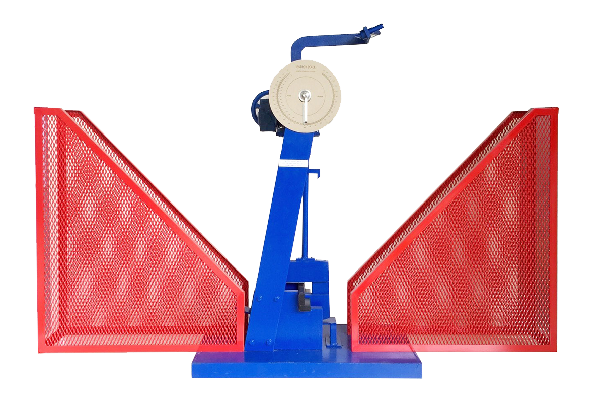
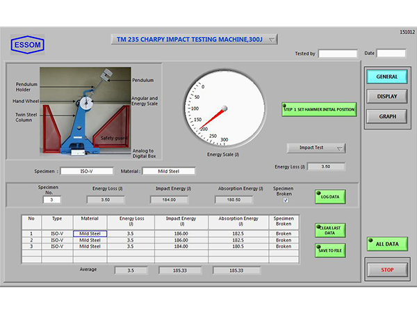
TM 235 CHARPY IMPACT TESTING MACHINE, 150/300 J
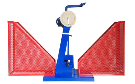
The impact testing machine is for determination of resistance to fracture of materials by Charpy test based on DIN50115 and DIN51222.
The machine is constructed with a heavy base and single support column. The pendulum is hung on ball bearings. Manual lifting of hammer is by two stage reduction gear. The impact energy can be adjustable for different capacity. A pendulum mechanical brake and safety guard are also provided.
Instruction manual is also included.
Determination of notched bar impact work.
Determination of notched bar impact strength.
Influence of notch form on impact work.
Influence of materials heat treatment, and temperature on impact work (optional).
| : 150 and 300 Joules |
| : 1 and 2 Joule |
| : 145o |
| : 5.378 m/s |
- Net (unpacked) Shipping Dimensions WxLxH: 60 x 95 x 140 cm
- Net Weight: Approx. 450 kg
| Furnace for material heat treatment experiment |
| Specimens (pack of 5). - Notch : ISO-V, ISO-U |
| Additional motorized lifting device and a speed reducer with 220V, 1 Ph, 50Hz. power supply instead of manual lifting with a speed reducer. |
| Eddy current brake. |
| Computer Interface (computer not included) |
| This includes TM232S and significant sensor(s) instead of analog measuring instrument(s), data acquisition (capture, display, graph and/or data export), additional software function for real-time data logging with computer interface unit and WiFi feature for data logging and real-time display remotely on smartphone (iOS and Android) |
- Other optional equipment, please contact manufacturer ([email protected])
| Learning Software |
| to support both online/offline training with data calculation and analysis by manual data entry from analog measuring instruments. |

TM 232 CHARPY IMPACT TESTING MACHINE, 25/50 J
The impact testing machine is designed for determination of resistance to fracture of materials by charpy test based on DIN51222.
The machine is constructed with a heavy base and support columns. The pendulum is hung on ball bearings. The impact energy can be adjustable for different capacity. A pendulum brake and safety guard are also provided.
Instruction manual is also included.
Determination of notched bar impact work.
Determination of notched bar impact strength.
Influence of notch form on impact work.
Influence of materials heat treatment, and temperature on impact work (optional).
| : 25 and 50 Joules |
| : 0.25 and 0.5 Joule with maximum pointer. |
| : 145o |
| : 3.825 m/s |
- Net (unpacked) Shipping Dimensions WxLxH: 40 x 65 x 120 cm
- Net Weight: Approx. 171 kg
| Furnace for material heat treatment experiment |
| Specimens (pack of 5). |
| Computer Interface (computer not included) |
| This includes TM232S and significant sensor(s) instead of analog measuring instrument(s), data acquisition (capture, display, graph and/or data export), additional software function for real-time data logging with computer interface unit and WiFi feature for data logging and real-time display remotely on smartphone (iOS and Android) |
- Other optional equipment, please contact manufacturer ([email protected])
| Learning Software |
| to support both online/offline training with data calculation and analysis by manual data entry from analog measuring instruments. |

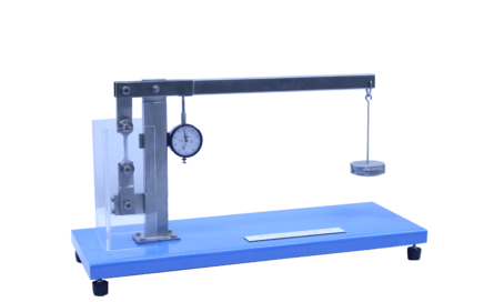
TM 221 CREEP TESTING MACHINE
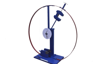
This equipment is used for testing materials with high creep such as lead and plastics.
A lever is pivoted to a column via ball bearing. Specimen is attached to one end of the lever while load is applied on the other end. Specimen extension is measured by a dial indicator. A glycol pack is provided to wrap the specimen and maintain the required test temperature.
Instruction manual is also included.
Creep phenomena of materials under different stresses and temperatures.
| : 8:1 |
| : Clear acrylic |
| : 1 lot. |
| : 10 mm x 0.01 mm graduation. |
| : -10 to 50°C |
| |
- Net (unpacked) Shipping Dimensions WxLxH: 25 x 65 x 40 cm
- Net Weight: Approx. 15 kg
| Lead (Pack of 10). |
| Poly Ethylene (Pack of 10). |
| Poly Vinyl Chloride (Pack of 10). |
| Computer Interface (computer not included) |
| This includes TM221S and significant sensor(s) instead of analog measuring instrument(s), data acquisition (capture, display, graph and/or data export), additional software function for real-time data logging with computer interface unit and WiFi feature for data logging and real-time display remotely on smartphone (iOS and Android) |
- Other optional equipment, please contact manufacturer ([email protected])
| Learning Software |
| to support both online/offline training with data calculation and analysis by manual data entry from analog measuring instruments. |